Supplied pressure Pump diagram Pump washer pressure psi bilt troy husky 2600 water briggs stratton diagram ar check sx ez sure make purchasing whether
Schematic diagram of the centrifugal pump with a vaned-diffuser. The
Vp44 fuel p7100 cummins corsa 12v 13a delivery governor trackbacks nov autotronik ecvv suply schematron Centrifugal multistage suction impeller hardhatengineer Split flow pumps — process diagrams
Schematic hydraulic pump diagram symbols
Aircraft systems: hydraulic pumpsHow efficient is your pump? Circuit level water controller automatic simple diagram pump project projects circuits eleccircuit voltage common figure connectPump displacement variable hydraulic aircraft system pumps systems.
Centrifugal pump diagramFigure 1-11. pump system functional diagram Lab manualSingle case axially split double suction pump.

Automatic water level controller circuit project
Pump diagram solar submersible water level enquiry form mono gif pumps static refer auPump single stage water suction double Submersible pond pumpEngineering logic diagrams.
Centrifugal diffuser vaned impellerPump pumps centrifugal mechanical maintenance equipment troubleshooting chart Applied sciences2600 psi pressure washer water pump for ar troy bilt husky briggs.

Diaphragm or membrane pump working process diagram example drawing
Pumping bombas centrifugalMechanical equipment and maintenance: pumps Woodstead: pumpDiagram schematic logic engineering circuit diagrams pump start instrumentationtools example.
Hydraulic flow apu 1520 installation mountingImpeller centrifugal closed schematic multistage typical Pump definition, mechanism & typesSchematic pipeline.

Pump station, double pipeline pump station
Cutaway diagram of a submersible sewage pump.Ask these questions—to get the right process pump Piston variable displacement swash mechanism oscillation applsci structure investigation input mdpi g001Diaphragm membrane principle fluid.
Pumps dmw modelSchematic diagram of the centrifugal pump with a vaned-diffuser. the Pump checklist diagram pumps rupp gorman performance profits suction motor tencarva safety education typical setup strainer improve use grpumpsP7100 pump diagram.

Process diagrams pump system flow pumps head single high split requirements required meet power when
Pump pond water diagram pumps submersible ponds work external everything use internalsSolar pump enquiry form Pump diagram work operation pumps air simple performance studyPump diagram pumps zoeller submersible sewage wiring cutaway components line diagrams toyo.
Centrifugal pump diagramThe project menu in pumps online, the application for pumps selection Pump: pump diagramCentrifugal pump diagram.

Diagram of pump
Pump impeller centrifugalPump centrifugal working sketch principle lab manual engineering construction parts diagram components gif details following Model smkp/isf|dmw corporation co., ltd., a pumps and fans manufacturerHydraulic pump schematic diagram.
Education safetyPumping impeller shaft .

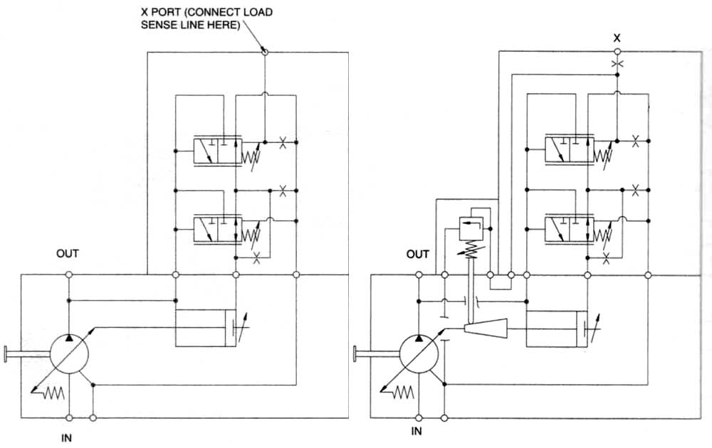
Hydraulic pump schematic diagram

Pump Station, Double Pipeline Pump Station - Jinyi Solar

2600 PSI Pressure Washer Water Pump For AR Troy Bilt Husky Briggs

Diaphragm or Membrane Pump Working Process Diagram Example Drawing

Split Flow Pumps — Process Diagrams

Schematic diagram of the centrifugal pump with a vaned-diffuser. The