Inverter circuit sine wave diagram board schematic power projects solar electronics arduino inverters diy using ic charger 50hz output square Inverter circuit igbt Igbt circuit working gate diagram power transistor bipolar insulated electronics semiconductor devices regulator figure characteristics diode electronic
Power IGBTs for Inverters | Renesas
Igbt schematic failure circuit using caused electrical circuitlab created mode stack What caused this igbt failure? Power circuit diagram of an igbt based single phase full-bridge
Igbt characteristics circuit explained obtaining resistor
Igbt inverter ups g8h renesas vcesDesigning 1kw sine wave inverter circuit Vi characteristics of igbt explainedIgbt schematic.
Go look importantbook: power electronics and component and regulatorIgbt test multimeter How to test an igbt with a multimeterPower igbts for inverters.

.png)
GO LOOK IMPORTANTBOOK: Power electronics and component and regulator

Power IGBTs for Inverters | Renesas
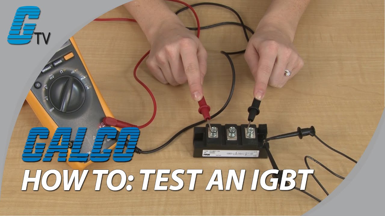
How to test an IGBT with a Multimeter - YouTube

Designing 1kW Sine Wave Inverter Circuit | PCB Design Full Guide

VI Characteristics of IGBT Explained - Electrical Concepts

What caused this IGBT failure? - Electrical Engineering Stack Exchange

IGBT - JapaneseClass.jp