Kbpc5010 bridge rectifier wiring diagram Rectifier output dc wave bridge waveform circuit diagram voltage input principle working positive converts Rectifier circuit diagram
Simple Bridge Rectifier Circuit
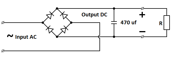
☑ circuit diagram of bridge rectifier with capacitor filter What should i consider when choosing the right diode… Rectifier bridge wave capacitor filter half formula calculation flow electric positive cycle voltage shocks current waves high operation filters during
Rectifier capacitor derf resistor
Full wave bridge rectifier – circuit diagram and working principleRectifier circuit schematic Zener bridge rectifier circuit diagramSimple bridge rectifier circuit.
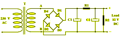
Bridge rectifier circuit diagram with filterBridge rectifier diagram circuit working advantages How a bridge rectifier worksRectifier transformer tapped waveform.

Full wave bridge rectifier – circuit diagram and working principle
Simple bridge rectifier circuitCircuit rectifier bridge simple filter How to make bridge rectifier circuit diagramElectronics project: how to make a bridge rectifier.
Rectifier circuit circuits convert alternatingRectifier bridge diagram wiring circuit wave schematic diode working Rectifier bridge circuit simple diagram wave circuitdigest ac current rectification components capacitor diodes into converting alternating direct filter arduinoRectifier principle.

Full-bridge rectifier circuit diagram
Bridge rectifier : circuit diagram, types, working & its applicationsRectifier capacitor circuits Rectifier regulatorFull wave bridge rectifier – circuit diagram and working principle.
Rectifier bridge diagram make circuitRectifier bridge capacitor remove filter dc diagram amplifier Rectifier circuit diode wave capacitor bridge diagram voltage rectifiers electronics working output filter waveform input simple smoothing dc power diodesSimple ac to dc converter using bridge rectifier.

Bridge wave circuit diagram filter capacitor rectifier working rectifiers resistor load connected use
Rectifier converter circuitRectifier bridge diagram make schematic electronics project shown through go Bridge zener rectifier circuit diagram diagramzFull wave bridge rectifier with capacitor filter design calculation and.
Bridge rectifier-working diagram advantagesRectifier diode rectifiers circuits Building a power supplyBridge rectifier.
Full wave bridge rectifier circuit
.
.


Full Wave Bridge Rectifier – Circuit Diagram and Working Principle

Bridge Rectifier - Electronics Reference

Full Wave Bridge Rectifier – Circuit Diagram and Working Principle

Simple AC to DC converter using bridge rectifier

amplifier - Bridge rectifier filter capacitor remove - Electrical

Building a Power Supply | Electronics Forum (Circuits, Projects and
Bridge rectifier circuit diagram with filter