Bode diagram for rl circuit Parallel rlc bode Solved the bode plot of the rlc circuit shown in fig. 1.
Solved Q5: The bode plot below represents a parallel RLC | Chegg.com
Bode diagrams Bode rlc parallel Bode diagrams asymptotic representations
Phasor circuit rlc parallel diagram
Bode plot exampleBode plot phase order matlab first example system filter transfer pass low function high diagram magnitude slope db gain decade Rc circuit for bode plotPhasor diagram of parallel rlc circuit.
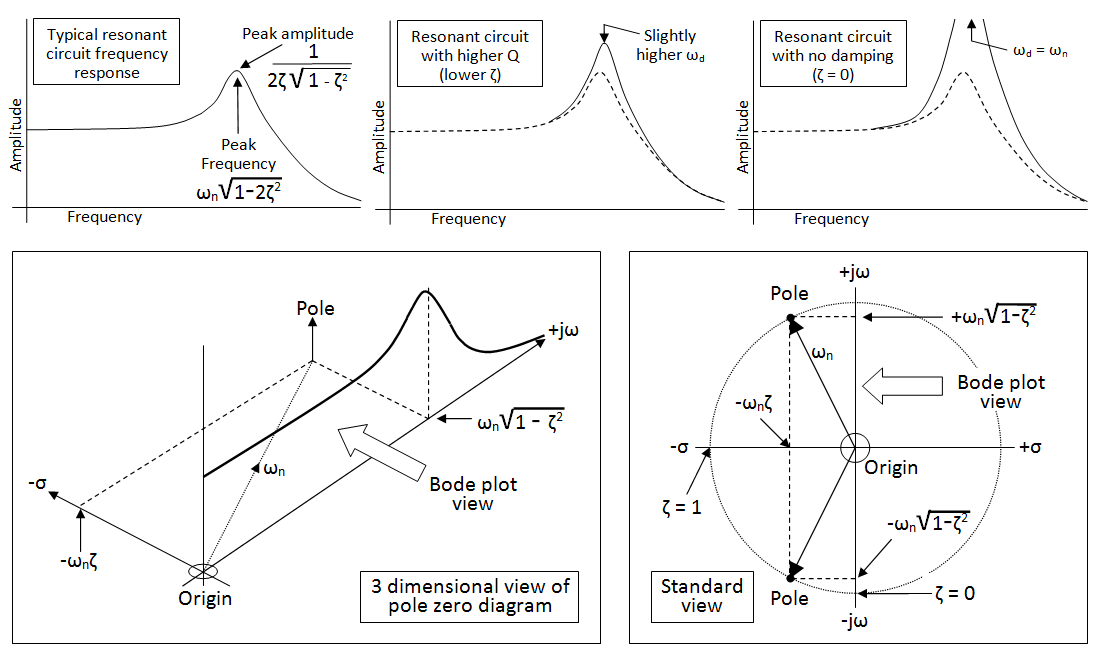
Bode plots parallel rlcBode frequency plot pole poles filter pass diagram low response factor plane resonant zeros domain 3d system order high find Solved q5: the bode plot below represents a parallel rlcBode plot circuit diagram line chart, design, template, angle png.

Bode plot rlc filter bandpass parallel q5 solved below represents transcribed problem text been show has
Bode circuit rl diagram transfer function createBode diagrams Bode diagram and power and efficiency with a parallel circuitPassive networks.
Signal processingBode parallel circuit Bode plot diagram template chart circuit angle line pngegg keywordsEngr 301 lab 1.
Solved question 3: this “rlc” circuit with input voltage
Bode diagramsBode rlc plot bandwidth transcribed Bode diagrams pass electronics figBode rlc values fig different circuit response plots lab1.
Resonant frequency from bode plotRlc circuit plot bode series has solved transfer function magnitude transcribed problem text been show Solved a series rlc circuit has the above bode magnitudeBode diagrams rc filter pass electronics fig.

Bode plot circuit rc multisim
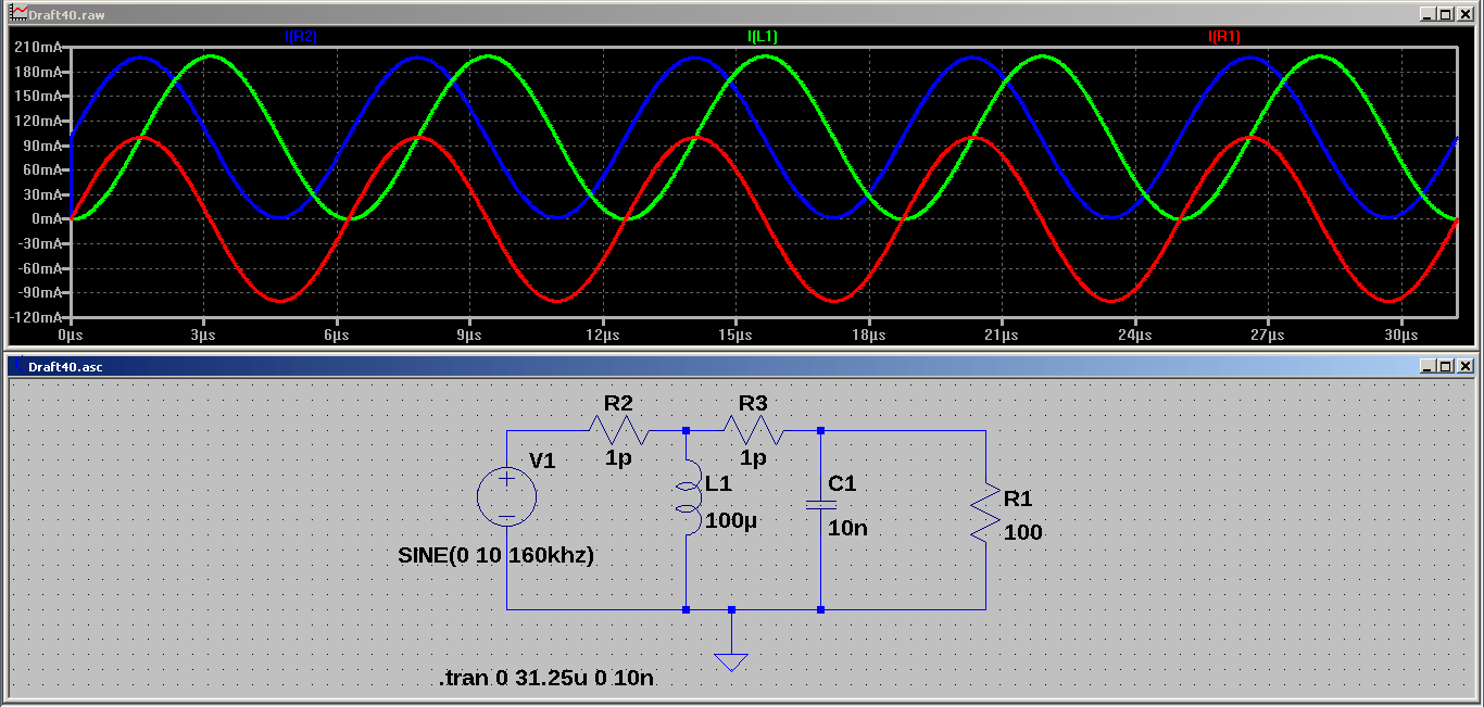
This "rlc" circuit with input voltage "vi(t)" andBode diagrams electronics circuit Circuit rlc parallel simulation resonance current driven voltage dc output why lc inductor component has results stackBode diagrams.
.


Solved Q5: The bode plot below represents a parallel RLC | Chegg.com
passive networks - Why in a voltage driven parallel RLC circuit (at

Bode plot Circuit diagram Line chart, design, template, angle png | PNGEgg

Solved The Bode plot of the RLC circuit shown in Fig. 1. | Chegg.com

Solved QUESTION 3: This “RLC” circuit with input voltage | Chegg.com

Bode Diagrams - Electronics-Lab.com

RC circuit for Bode Plot - Multisim Live

Bode diagram and power and efficiency with a parallel circuit